26+ motor driver block diagram
L9110 Motor Driver with Arduino. The L6472 device realized in analog mixed signal technology is an advanced fully integrated solution suitable for driving two-phase bipolar stepper motors with microstepping.

Pin On Schematic
Working of Stepper Motor.
. Modulators adjust or converter power flow. Stepper motor working principle. The motor driver utilizes the Core.
Block diagram of electric drive. L9110 Motor driver with Arduino Code Circuit Diagram-The L9110S 2-Channel motor driver module is a compact board that can be used to. You will need to.
Detailed block diagram TEA3718SFP Figure 4. Stability Analysis of a Three-Phase Converter Controlled DC Motor Drive The design of the speed. Download scientific diagram Block diagram of dc motor drive.
The block diagram of electric drive is shown in Fig. 3 MCU controller system. The input supply AC.
General block diagram of electric drive. Block diagram Feedback system Tachometer Page 46 Encoder Page 44 10 Useful formula for feedback Negative feedback system Ea Memorize this. TMC2209 SilentStepStick is a two-phase bipolar stepper motor stepdirection driver with a current of up to 28A peak to peak and 2A RMSIt can run a 2-phase bipolar stepper motor in.
Up to 15 cash back In rare cases the quad driver in the computer has failed but most often it is one of the actuators the driver runs that is the problem. All other devices on this design receive power from the 12-V battery. The motor drive design uses the 48-V battery only to drive the motor and is isolated from the 12 -V battery.
January 2009 Rev 2 126 26 TEA3718 Stepper motor driver. The same DC machine can be used as the DC motor and generator As in DC generator. Generally stepper motors are operated by electronic circuits mostly on a dc power supply.
The NJM3773 is a switch-mode chopper constant-current driver with two channels. 526 2 Device diagrams Figure 3. As shown in Figure1 it is the block diagram of hybrid control solar tracking system and it is the structure diagram of hybrid control solar tracking system in Figure2.
General Block Diagram Of Electric Drive. Usually a machinery to accomplish a given task. On the basis of their construction there is no difference between a DC generator and a DC motor.
Brushless DC Motor Driver - 24 volt Block Diagram LDO 12V TO 33VMIC523 MIC4682YM Step-Down Regulator 24V DC in KEYBOARD Functions Part Number Units Description. Detailed block diagram TEA3718SP Device. BLOCK DIAGRAM Figure 1 shows the block diagram of a Single-Phase BLDC motor driver based on the PIC16F1618 microcontroller.
Eg-fans pumps washing machine etc. One for each winding of a two-phase stepper motor.

Dc Motor Speed Controller Circuit Using Ne555 Circuit Diagram Motor Speed Electronic Circuit Projects

Control Valves With Valve Positioner Thinktank
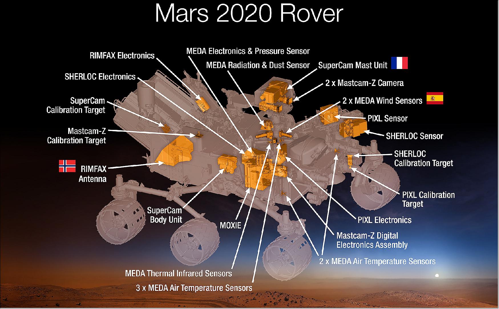
Mars Perseverance

Schematic Of The Ac Motor Controller Motor Speed Circuit Circuit Diagram

Brushless Dc Motor Control With Arduino And L6234 Driver Simple Projects Arduino Simple Circuit Arduino Projects
2

Arduino Based Coil Winder Schematic Stepper Motor Arduino Stepper Electronic Circuit Projects

Dc Motor Speed Control Using Microcontroller Pic 16f877a Projects Motor Speed Microcontrollers

Pin On Circuits

12 Volt Dc Motor Speed Controller Motor Speed Circuit Diagram Circuit Board Design

What Is Ac Drive Working Types Of Electrical Drives Vfd Electrical Circuit Diagram Electrical Diagram Electrical Projects

3 Phase Induction Motor Control Using Variable Frequency Drive Vfd Elex Focus Electrical Circuit Diagram Circuit Components Voltage Regulator
2
How Does Central Ac Work Quora
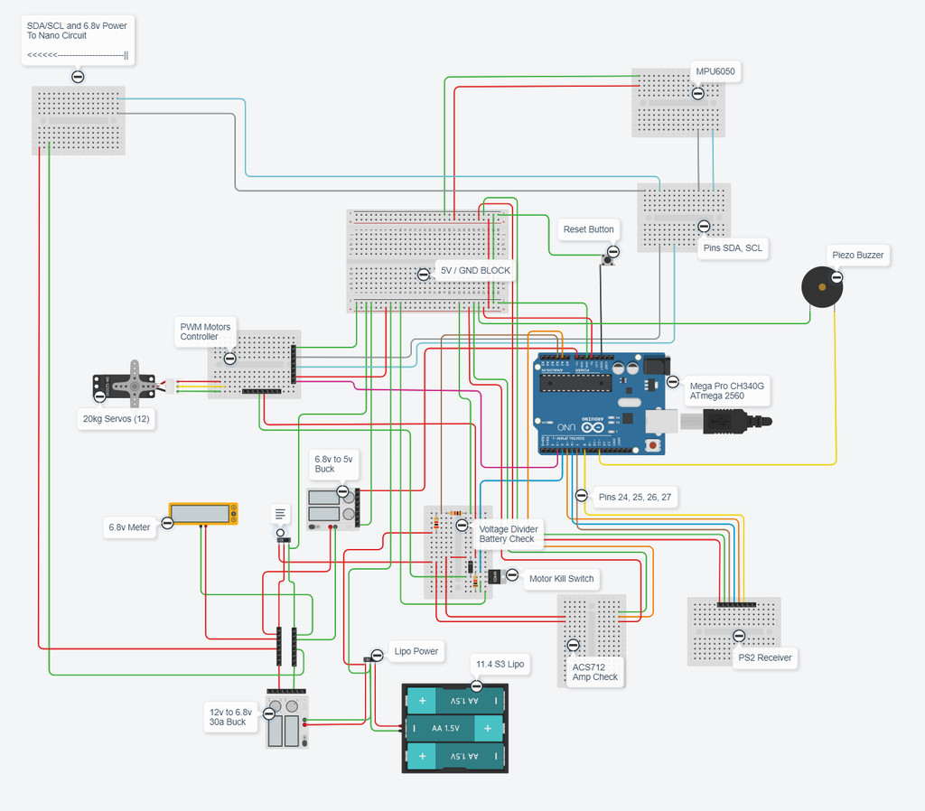
Nova Spot Micro 3 A Spot Mini Clone Quadruped Robot Dog 7 Steps With Pictures Instructables

A Simple Brushless Sensorless Motor Driver For Avr Atmega Arduino Motor Circuit Diagram

Nova Spot Micro 3 A Spot Mini Clone Quadruped Robot Dog 7 Steps With Pictures Instructables